Boring Basics
Boring is an internal turning operation used to make holes bigger. Single-point cutting tools—boring bars—are the most commonly used tools.
As a boring bar cuts, the cutting force may be applied far from where the tool is supported. The unsupported distance between where the cut occurs and where the boring bar is clamped is its overhang. With more overhang, the boring bar can machine a deeper hole. But more overhang also increases the risk of excessive deflection and vibration. To bore deep holes effectively, a boring bar needs to have high stiffness.
The stiffness takes two forms. Dynamic stiffness resists vibration. Static stiffness resists deflection. This article focuses on the static stiffness. Just understanding the basic equation that governs a boring bar’s deflection can reveal what steps would be most effective at making a boring process stiffer.
Cutting Forces Acting On The Boring Bar
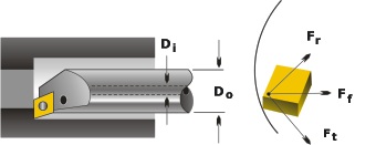
The cutting force acting on the boring bar can be defined in terms of three components: tangential force, feed force, and radial force. (See Figure 1, below.)
Captions:
Ft – tangential force Fr – radial force Ff – axial force Do – outside diameter of the boring bar Di – boring bar inside diameter for coolant
In boring, the tangential cutting force is the largest. It acts perpendicular to the cutting insert rake surface and pushes the boring bar “downward”—that is, below the centerline.
The feed force is the second largest. It acts parallel to the centerline and does not deflect the boring bar. Typically, the strength of the feed force is about 50 to 60 percent that of the tangential force.
The radial force is perpendicular to both of these forces and pushes the bar away from side of the bore. This force is about 25 to 30 percent of the tangential force.
Thus the boring bar sees deflection in both the tangential and radial directions.
Deflection Of The Boring Bar
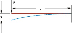
A boring bar’s deflection is similar to that of a cantilever beam. This is a beam with a fixed support at one end and free portion, or cantilever, on the other. (See Figure 2, below.) Because of the similarity, the formula describing a cantilever beam’s deflection will also describe a boring bar:
(Formula 1) Y = (F x L3) / (3E x I)
Where. . .
Y = tangential or radial deflection, in inches (in) or millimeters (mm)
F = tangential force (Ft) or radial force (Fr), in pounds (lb) or newtons (N)
L = unsupported length of the bar, or overhang, in inches or mm
E = modulus of elasticity in tension, in psi or N/mm2
I = bar’s cross-sectional moment of inertia, in in4 or mm4
Captions:
Ft – tangential force Fr – radial force Ff – axial force Do – outside diameter of the boring bar Di – boring bar inside diameter for coolant
In most cases, boring bars are round bars with solid or tubular cross sections. The last term in the list above, moment of inertia (I), is calculated using formula 2 for a solid cross section or formula 3 for tubular cross section. A boring bar with through-tool coolant would have a tubular cross section.
(Formula 2) Y = (F x L3) / (3E x I)
(Formula 3) Y = (F x L3) / (3E x I)
Where. . .
Do = bar outside diameter, in inches or mm
Di = bar inside diameter for coolant, in inches or mm
Calculation of the tangential force (Ft) in formula 1 includes a factor for units. Tangential force in pounds can be calculated as:
(Formula 4) Y = (F x L3) / (3E x I)
Tangential force in newtons can be calculated as:
(Formula 5) Y = (F x L3) / (3E x I)
Where. . .
396,000 = conversion factor, in lb·in/hp·min
1,000 = conversion factor, in N·cm/kW·sec
d = depth of cut, in inches or mm
f = feed rate, in inches per revolution (ipr) or millimeters per revolution (mm/rev)
Kp = power constant of the workpiece material in hp/in3/min or kW/cm3/sec
Radial cutting force (Fr) can be found as:
(Formula 6) Y = (F x L3) / (3E x I)
Recommendations
Formula 1 suggests all of the following recommendations for improving a boring bar’s static stiffness:
- Select boring bar overhang to be as short as possible.
Reason: Overhang gets cubed in the formula. Even a small additional amount of overhang can significantly increase deflection.
- Machine at an overhang-to-diameter ratio of no more than 3.5 for steel-shank boring bars . . . 5 for heavy metal shanks . . . and 8 for carbide shanks. These numbers have to do with the relative modulus of elasticity (E) of each of these materials. When the elastic modulus is higher, deflection decreases. Elastic moduli for common boring bar materials are:
Material Pressure Steel 28 to 30 million psi Heavy metals 45 to 52 million psi Cemented carbides
(10 to 15 percent cobalt content)80 million psi Cemented carbides
(3 to 8 percent cobalt content)90 million psi - Select boring bar diameter to be as large as possible.
Reason: The deflection of the bar decreases as the moment of inertia of the bar cross section. And formulas 2 and 3 show that the moment of inertia gets larger when the diameter increases.
- Ignore boring bar hardness.
Reason: This characteristic doesn’t appear in any of the equations. A common mistake is to assume that a boring bar with a higher hardness—or one made from a higher quality of steel—will deflect less. In fact, the material property that determines deflection is modulus of elasticity. Hardness doesn’t figure in.
Example Calculations
Givens
- Boring bar characteristics
Do = 1.00 in (25.4 mm)
Di = 0.156 in (3.96 mm)
L = 5.00 in (127 mm)
E = 30 x 106 psi (207000 N/mm2)
Shank made of 4340 alloy steel - Workpiece characteristics
AISI 4140 alloy steel, hardness 250 HB
Kp = 0.84 hp/in3/min (2.29 kW/cm3/sec) (from Machinery’s Handbook, 26th Edition, Industrial Press Inc.) - Cutting conditions
d = 0.080 in (2.03 mm)
f = 0.008 ipr (0.203 mm/rev)
Calculating cutting forces:
Using formula 4, Ft = 396000 x 0.08 x 0.008 x 0.84 = 212.9 lb
Using formula 6, Fr = 0.3 x 212.9 = 63.9 lbMoment of inertia is calculated using formula 3:
I = x (1.04 – 0.1564)/64 = 0.049 in4.Deflection of the boring bar is calculated using formula 1:
Yt = 212.9 x 53/(3 x 30 x 106 x 0.049) = 0.0060 in
Yr = 63.9 x 53/(3 x 30 x 106 x 0.049) = 0.0018 in - Boring bar characteristics